
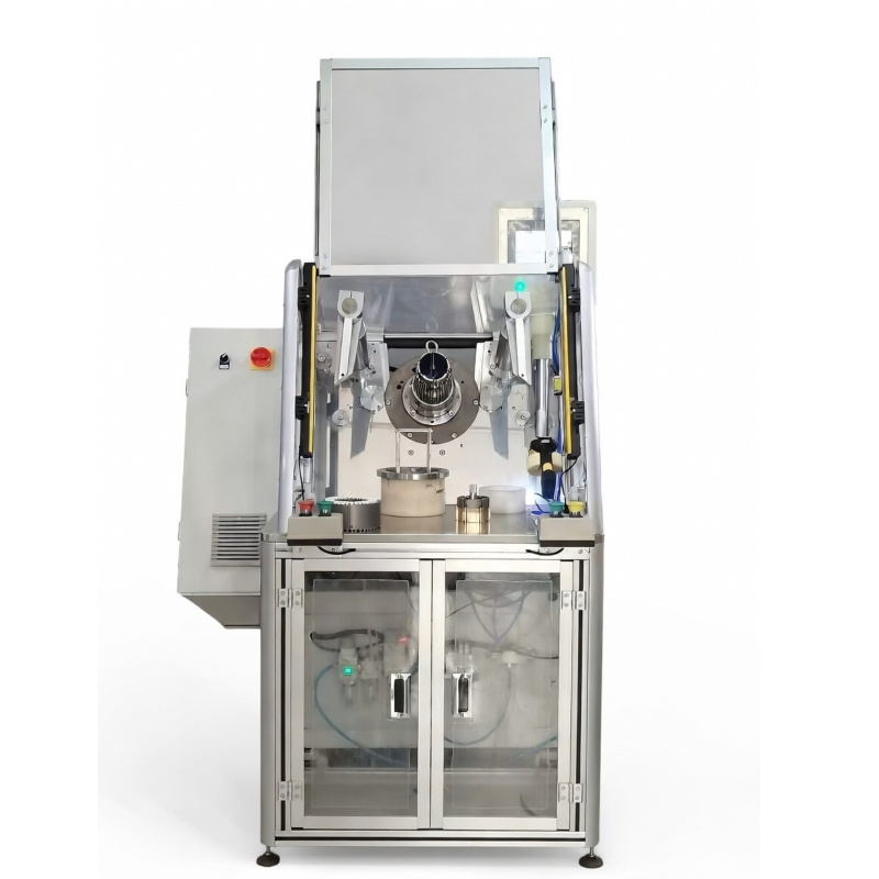
This stator coil inserter is designed to place coils and slot wedges into stator slots in one operation. It brings the two actions together at the insertion station, so the coil and wedge are handled as one defined process rather than as separate manual steps. For small induction-motor stators, the machine provides a practical route for arranging the insertion stage around the workpiece dimensions, slot pattern, wire type, and selected tooling.
The machine uses a servo-driven insertion mechanism for the coil and slot wedge. Its wedge material is fed through a stepper-motor paper-feeding system. An HMI provides access to parameter settings, allowing the operator to set insertion-related parameters and adjust insertion speed or the slot-wedge feeding method for the applicable motor slot fill factor and wire type. In plain terms, the adjustment points help the equipment follow the conditions of the stator being processed; they do not remove the need to match the tooling and settings to the workpiece.
As a stator coil inserter, this equipment is intended for a defined coil-and-wedge insertion stage. It can be considered within motor stator automation where the surrounding operations, material flow, and handoff conditions are established separately. The equipment capability is one part of the line; upstream coil preparation and downstream stator operations remain part of the wider production arrangement.
| Specification | Confirmed value |
|---|---|
| Stator outside diameter | Up to 160 mm |
| Stator inside diameter | 30–110 mm |
| Stator core length | 10–150 mm |
| Tooling stroke | Up to 60 mm |
| Applicable wire | Copper or aluminum |
| Stator slots | 8–48 |
| Power supply | 380 V, 50/60 Hz, 3 kW |
| Approximate machine weight | 600 kg |
| Dimensions | 1850 × 650 × 1700 mm |
These dimensions establish the working envelope for the stator coil inserter. They should be reviewed alongside the actual stator drawing, slot geometry, winding arrangement, and tooling requirements before configuration. A stated range is useful for initial fit, while the final setup depends on the specific stator and coil conditions.
The outside-diameter limit, inside-diameter range, core-length range, and slot count should be read as related conditions rather than isolated numbers. For example, a stator can fall within one published dimension while still needing its coil shape, wedge path, and fixture contact points considered for the intended insertion operation. Copper and aluminum wire are both listed as applicable wire types, but the actual winding arrangement remains an important setup input. The 380 V, 50/60 Hz, 3 kW supply requirement, approximate 600 kg machine weight, and 1850 × 650 × 1700 mm overall dimensions are useful for planning the machine location and utility connection.
A slot wedge insertion machine is most useful when its wedge feed, insertion route, and tooling are aligned with the stator design. Changeover is not just a setup term; it affects which parts, settings, and workpiece details should be checked when motor variants change. Observing which components and parameters are rechecked at changeover can help define a clearer work instruction.
Motor stator automation is often discussed as a broad production goal. Here, the focus is narrower and concrete: the machine handles the coil-and-wedge insertion operation described above. A larger automated cell may include other stations, but they are not represented as included with this machine. This distinction makes it easier to discuss the equipment around the actual insertion task.
At the insertion station, an operator can use the HMI to work with the parameters identified for the process. Insertion speed and the wedge feeding method can be adjusted according to the stated motor slot fill factor and wire-type conditions. These settings are part of the machine’s available operation; their selected values need to suit the part being run. A tooling change is the stated route for product changeover, so a different stator variant should be considered with the matching tooling rather than assuming one arrangement applies to every motor family.
The supplied product information identifies small induction motors as the intended application area. Examples include motors used in air conditioners, washing machines, compressors, fans, generators, and water pumps. Across these applications, the relevant starting point is whether the stator falls within the documented dimensional and slot ranges and whether its coil, insulation, and wedge requirements can be supported by the selected tooling.
For induction motor manufacturing, the machine can serve as the coil-and-wedge insertion station after the appropriate coil preparation and before the next stator operation. The practical value is a defined sequence in which the coil and wedge are inserted together, with parameter access available through the HMI. It is not a claim that every motor design uses the same settings; the wire type, fill factor, slot layout, and tooling conditions remain important inputs.
This stator coil inserter may also be relevant to production teams planning a repeatable insertion step for several small-motor variants. Machines with more functions do not automatically make a current process a better fit. The key question is whether the documented stator range, required wedge feed method, and tooling approach correspond to the intended workpiece.
For air-conditioner, washing-machine, compressor, fan, generator, and water-pump motor work, the machine description gives a shared reference point: coil and wedge insertion occur in one operation. The resulting production sequence should still reflect the individual stator’s geometry and the selected process route. A stator coil inserter supports the documented insertion stage, while the full route for insulation, winding preparation, forming, testing, and later operations is defined by the production arrangement.
To discuss a slot wedge insertion machine for a particular stator, provide the stator outside diameter, inside diameter, core length, slot count, wire type, coil arrangement, and the required wedge material or feeding condition. These inputs connect the published machine range to the actual part. They are especially useful when a tooling changeover is expected between motor variants.
For motor stator automation planning, it is also helpful to describe where the insertion station will sit in the process flow and what condition the stator has at handoff. This supports a focused discussion of process connections without suggesting that the machine itself covers unlisted upstream or downstream equipment. For induction motor manufacturing, a clear description of the motor family and production sequence helps keep the coil-and-wedge insertion discussion tied to the correct operation.
The keywords CE-certified stator equipment may be relevant to projects with a specific compliance requirement. Certification status, scope, and documentation should be confirmed for the requested configuration before it is treated as part of an order requirement. This stator coil inserter page therefore concentrates on the stated operating features and dimensions rather than making an unverified certification claim.
Send the workpiece details and desired insertion conditions to discuss whether this stator coil inserter and its tooling approach suit your coil-and-wedge operation. The machine combines coil insertion, wedge feeding, servo-driven insertion, HMI settings, and tooling-based changeover in a focused station for the documented small-stator range.

 EN
