
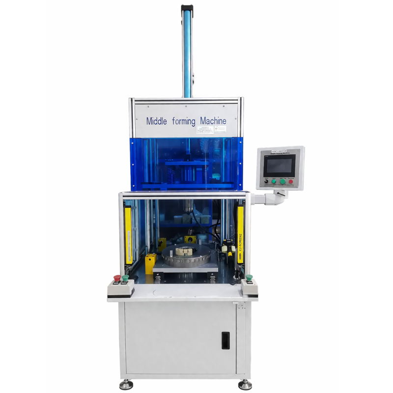
This hydraulic stator middle forming machine is designed for the middle-forming stage of stator production before lacing. It combines a hydraulic drive system with industrial PLC control to form the stator winding area through internal expansion and external wrapping. The purpose is straightforward: organize the enameled wire around the stator teeth and prepare a consistent form for the following lacing operation.
For manufacturers working with defined stator dimensions, the machine provides a practical stator forming machine arrangement with a stated outer-diameter limit of up to Ø210 mm, an inner-diameter range of Ø80–Ø150 mm, and a stator core-length range of 80–200 mm. These published limits provide a clear starting point for matching a workpiece to the machine. The winding layout, insulation arrangement, and tooling requirements should be confirmed for each application.
The machine uses a single tooth guard at each slot to guide and organize enameled wire during the forming operation. This arrangement is intended to help reduce wire escape and fly wires while maintaining the required creepage-distance relationship described in the product information. Internal expansion and external wrapping work together to shape the winding end before stator lacing.
PLC control gives operators a defined control platform for the forming sequence. In a motor manufacturing automation workflow, the forming stage is not only about changing the winding shape; it also affects how the stator presents to the next operation. A neat, organized winding end can make the lacing step easier to approach. The machine’s role should be considered together with the incoming stator condition, the selected tooling, and the downstream process route.
Although a hydraulic coil winding equipment search may cover several types of machinery, this model is specifically a hydraulic forming machine rather than a coil winding machine. Its described function is to form and organize an already wound stator. That scope distinction helps keep the equipment choice aligned with the actual process stage.
More machine functions do not automatically make a current process a better fit. For a defined middle-forming task, it is more useful to compare the stator size, winding condition, and required downstream handoff with the stated machine range. If a project requires special tooling, different wire arrangements, or integration with other stations, those conditions should be discussed before selecting a configuration.
| Item | Published Value |
|---|---|
| Stator outer diameter limit | ≤ Ø210 mm |
| Stator inner diameter limit | Ø80–Ø150 mm |
| Stator core length limit | 80–200 mm |
| Cylinder displacement | 20 L/min |
| Power supply | 380 V, 50/60 Hz, 3.75 kW |
| Machine weight | Approximately 600 kg |
| Dimensions (L × W × H) | 1850 × 1200 × 2700 mm |
These values describe the supplied machine information and are useful for early application matching. The power supply, footprint, and approximate weight can be reviewed when planning placement. Workpiece dimensions alone do not define the full setup: the stator construction and forming requirement remain important when determining whether this stator forming machine suits a particular product.
The machine is listed for stator-related production in fuel automotive, new energy vehicle, industrial, elevator, home-appliance, pump, and fan applications. In each case, the forming operation is relevant where wound stators need their wire ends organized and shaped before the lacing stage. A PLC-controlled stator former can be considered where the workpiece falls within the published size range and the production sequence includes this middle-forming step.
For automotive and new-energy vehicle motor work, confirm the specific stator dimensions and winding arrangement. For pumps, fans, elevators, home appliances, and industrial motors, identify the same practical handoff points: the workpiece entering the machine, the required formed condition, and the next operation. This approach keeps motor manufacturing automation focused on the individual operation rather than assuming a complete production line is included.
A stator forming machine is used where the required task is to shape and organize a wound stator before lacing. This stator forming machine is intended for the middle-forming operation described in the supplied machine information. In a defined route, a stator forming machine can be positioned after winding and before the next winding-end operation. The actual stator forming machine setup depends on the workpiece dimensions, wire arrangement, insulation details, and the formed condition required at the next station.
For teams planning motor manufacturing automation, this stator forming machine provides a focused forming function rather than a complete line. Motor manufacturing automation may include several separate stations, and the stator forming machine addresses only the stated middle-forming stage. The available hydraulic drive and PLC control are relevant when a controlled forming sequence is needed. In motor manufacturing automation planning, confirm the incoming condition and downstream lacing requirement rather than assuming that adjacent equipment is included.
The phrase hydraulic coil winding equipment can describe a broad equipment group. This hydraulic coil winding equipment is described as a forming machine for stators that have already been wound, not as a winding station. When comparing hydraulic coil winding equipment with a forming operation, match the quoted function to the actual production step. A PLC-controlled stator former can support an organized forming sequence when the stator falls within the published dimensional range. The PLC-controlled stator former should be discussed with the intended tooling and wire layout.
Several production applications can use a stator forming machine, including the listed automotive, new-energy vehicle, industrial, elevator, home-appliance, pump, and fan sectors. For each application, the stator forming machine should be matched to the stated outer diameter, inner diameter, and core length. A hydraulic coil winding equipment inquiry can include the workpiece dimensions and process position. That information makes the motor manufacturing automation discussion more specific and keeps the PLC-controlled stator former focused on its stated forming role.
For a new project, share the winding pattern and stator dimensions before finalizing a stator forming machine configuration. The hydraulic coil winding equipment scope, tooling arrangement, and PLC-controlled stator former sequence can then be considered for the required operation. This is a practical way to connect the machine’s published specifications with a real middle-forming task.
This hydraulic stator middle forming machine offers a defined hydraulic and PLC-controlled approach to shaping wound stators before lacing. Its published dimensions, power requirement, and workpiece limits make it possible to begin a focused application discussion. Share the stator outer diameter, inner diameter, core length, winding details, and intended process position to discuss machine fit, tooling, and configuration for your forming operation.

 EN
