
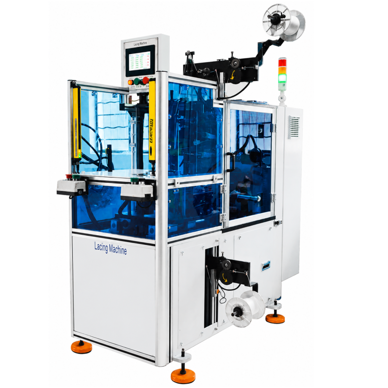
This Servo Double-head Coil Lacing Machine is designed for automatic lacing of coil ends on both sides of a stator. Its vertical stator loading arrangement combines a pressing device with automatic feeding, wire cutting, and wire feeding functions. Dual needles lace both coil ends simultaneously, placing the lacing operation in one compact piece of industrial motor manufacturing equipment. For a stator lacing machine comparison, this product is defined by its dual-head arrangement, servo-controlled motion, and stated dimensional working range.
The servo-driven system controls hook rotation for wire hooking and stator indexing. On the six-axis model, it also controls coil-height adjustment. These stated functions give the machine a clear role in a lacing operation where the workpiece, coil arrangement, and requested lacing pattern should be considered together. The listed servo lacing integration capabilities apply when a production route needs controlled indexing and coordinated wire-handling functions at the lacing station.
A stator lacing machine comparison can begin with the stator dimensions and the required lacing sequence. This model is listed for stator outside diameters up to 190 mm, inside diameters from 40 to 100 mm, and stator core lengths from 18 to 160 mm. Coil height is listed as up to 45/65 mm. Those limits provide a practical starting point for matching a workpiece to the machine; the final suitability depends on the actual stator and process arrangement.
The human-machine control panel supports slot-by-slot lacing, alternate-slot lacing, skip-slot lacing, and various fancy lacing patterns. Pattern flexibility is not only a control feature: it affects how a defined stator process can be set up for the selected coil-end requirement. The machine should be considered alongside stator orientation, upstream loading, downstream handling, and other connection conditions that apply to the planned line.
Compact layout and tooling changeover are useful operational considerations for this machine. The supplied product information describes a compact structure, easy operation, low noise, and quick tooling changeover. These points describe the machine concept, while fixture details and the exact process route should be confirmed for the intended stator type. Using the same workpiece conditions for every option makes a lacing-equipment discussion more useful.
| Specification | Listed Value |
|---|---|
| Stator outside diameter | Up to 190 mm |
| Stator inside diameter | 40–100 mm |
| Stator core length | 18–160 mm |
| Coil height | Up to 45/65 mm |
| Cycle time | 0.5 sec/stitch |
| Power supply | 380 V, 50/60 Hz, 4.5 kW |
| Machine weight | Approximately 600 kg |
| Dimensions | 1500 × 650 × 1700 mm |
The listed 0.5 sec/stitch cycle time is a machine specification, not a statement of a complete production-line result. It is useful to distinguish an individual machine cycle from surrounding material flow, operator tasks, and stator changeover conditions. This distinction keeps the lacing station’s stated capability clear when reviewing industrial motor manufacturing equipment.
These functions form the practical basis for the listed servo lacing integration capabilities. They describe what the equipment is intended to control at the lacing station, while material, tooling, and production-line arrangements remain application-specific. The available patterns, dimensional limits, and requested level of coordinated motion are useful factual points for an equipment discussion.
The supplied application list includes fuel automotive, new energy vehicle, industrial, elevator, home appliance, pump, and fan motor work. In each case, the machine is positioned for the coil-end lacing stage of a stator process. Application fit should be related to the actual stator diameter, core length, coil height, and pattern requirement rather than inferred solely from the industry name.
For automotive and new-energy motor production, a stator lacing machine comparison can start with the specified stator range and the required coil-end pattern. For pumps and fans, the same review can focus on whether workpiece dimensions fall within the listed limits and how the lacing station fits the existing process. Elevator and home-appliance motor programs can likewise use the stated dual-needle operation and selectable patterns as defined discussion points.
Where repeatable execution is important, document the actual stator dimensions and lacing sequence before deciding on a configuration. The listed dimensional limits explain the machine’s working range; they do not replace confirmation of tooling or workpiece handling. This practical separation helps connect machine features with the details that shape a specific motor process.
When using a coil lacing ROI calculator, treat the machine’s stated cycle time and the actual production conditions as separate inputs. A coil lacing ROI calculator can organize a discussion about output assumptions, but it does not replace confirmation of tooling, workpiece handling, or the requested lacing pattern. Provide the stator drawing or key dimensions, the required pattern, and the current process sequence so the machine scope can be discussed accurately.
Share the infeed and outfeed conditions, stator orientation at the lacing station, and any expected changeover needs. This makes it easier to relate the listed servo controls and automatic wire-handling functions to the intended operation. It also provides a practical basis for a stator lacing machine comparison without reducing the discussion to isolated labels.
If your project calls for a CE-certified coil lacing supplier, state the required certification documents and destination-market expectations in the inquiry. A CE-certified coil lacing supplier discussion should also include the intended machine configuration and project requirements. Sharing the workpiece data early keeps the conversation focused on the stated specifications and applicable process needs.
Contact us with your stator OD, ID, core length, coil height, lacing pattern, and line connection details. These inputs help frame a production discussion, clarify the requested servo lacing integration capabilities, and identify whether this Servo Double-head Coil Lacing Machine suits the intended application. Include any certification requirement with the inquiry so the relevant documentation scope can be addressed.

 EN
