
Motor shaft selection and installation represent critical aspects of mechanical engineering that directly impact equipment performance, reliability, and operational lifespan. Whether you're working with automotive applications, household appliances, power tools, or industrial equipment, understanding the fundamental principles of motor shaft design and implementation ensures optimal power transmission and reduced maintenance costs. Modern manufacturing demands precise motor shaft specifications that align with specific torque requirements, rotational speeds, and environmental conditions.
The complexity of motor shaft applications continues to evolve as industries push toward higher efficiency standards and more demanding operational parameters. From precision instruments requiring micro-level tolerances to heavy-duty industrial machinery handling substantial loads, the motor shaft serves as the backbone of mechanical power transfer systems. Engineers and technicians must consider multiple factors including material properties, surface treatments, dimensional accuracy, and compatibility with various motor types to ensure successful implementation.
Understanding Motor Shaft Fundamentals
Core Design Principles
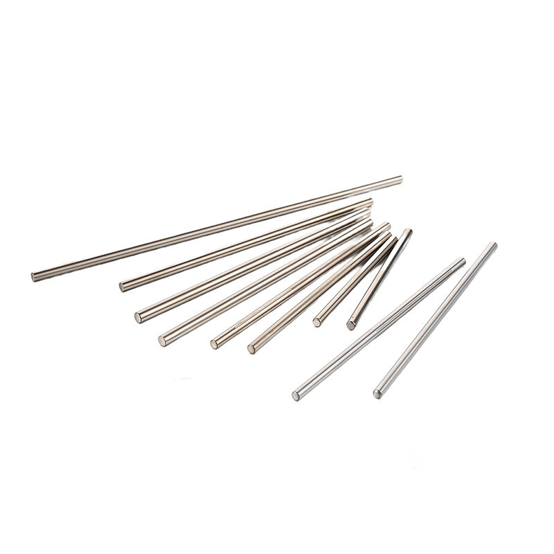
The motor shaft functions as the primary rotating component that transfers mechanical energy from the motor's rotor to external loads or driven equipment. This critical component must withstand various forces including torsional stress, bending moments, and axial loads while maintaining precise rotational accuracy. Engineers design motor shaft geometries to optimize strength-to-weight ratios while ensuring compatibility with bearings, couplings, and other connected components.
Material selection plays a crucial role in motor shaft performance, with common choices including carbon steel, alloy steel, stainless steel, and specialized materials for unique applications. The motor shaft diameter, length, and surface finish must align with specific torque transmission requirements and operating conditions. Heat treatment processes such as induction hardening, case hardening, or through hardening enhance the motor shaft's durability and resistance to wear.
Material Properties and Selection
Steel grades commonly used for motor shaft manufacturing include AISI 1045, AISI 4140, and stainless steel variants depending on environmental requirements. Carbon content directly affects the motor shaft's hardness, strength, and machinability, with higher carbon content providing increased strength at the expense of ductility. Alloying elements such as chromium, nickel, and molybdenum enhance specific properties like corrosion resistance, fatigue strength, and high-temperature performance.
Surface treatments significantly impact motor shaft longevity and performance characteristics. Chrome plating provides corrosion resistance and reduced friction, while nitriding processes create hard, wear-resistant surfaces. The motor shaft's surface roughness specification typically ranges from Ra 0.4 to Ra 1.6 micrometers depending on the application requirements and mating component interfaces.
Motor Shaft Types and Applications
Automotive Industry Applications
Automotive motor shaft applications span from starter motors and alternators to electric power steering systems and HVAC blower motors. These components must withstand temperature extremes, vibration, and exposure to automotive fluids while maintaining reliable operation over extended service intervals. The motor shaft in automotive applications typically features specialized coatings or treatments to resist corrosion from road salt and environmental contaminants.
Electric vehicle applications place additional demands on motor shaft design due to higher rotational speeds and continuous duty cycles. The motor shaft must accommodate permanent magnet rotors or induction motor assemblies while providing precise balance to minimize vibration and noise. Manufacturing tolerances for automotive motor shaft components often require precision grinding and dynamic balancing to meet stringent quality standards.
Industrial and Power Tool Applications
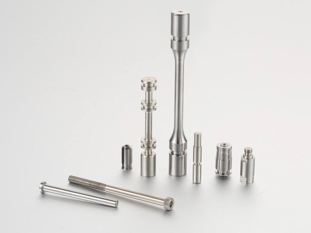
Industrial motor shaft applications encompass a broad range of equipment including conveyor systems, pumps, compressors, and manufacturing machinery. These environments demand robust motor shaft designs capable of handling continuous operation, varying load conditions, and potential shock loads. The motor shaft specifications for industrial use typically include provisions for keyways, splines, or other power transmission features.
Power tool applications require motor shaft designs that balance performance with cost-effectiveness while maintaining compact dimensions. Cordless drill motors, angle grinders, and reciprocating saws utilize specialized motor shaft configurations optimized for high-speed operation and intermittent duty cycles. The motor shaft in these applications often incorporates integrated cooling features or specialized bearing surfaces to manage heat generation during high-demand operation.
Selection Criteria and Specifications
Load and Torque Requirements
Determining appropriate motor shaft specifications begins with accurate load analysis including steady-state torque, peak torque conditions, and dynamic loading scenarios. Engineers must calculate the required motor shaft diameter using established formulas that consider material properties, safety factors, and deflection limits. Torsional stress calculations ensure the motor shaft can handle maximum expected torque without exceeding material yield strength or fatigue limits.
Bending stress analysis becomes critical for motor shaft applications with overhung loads or extended shaft lengths. The motor shaft must resist deflection that could cause bearing misalignment, increased wear, or vibration issues. Computer-aided design tools and finite element analysis help optimize motor shaft geometry for specific loading conditions while minimizing material usage and manufacturing costs.
Speed and Frequency Considerations
Rotational speed directly impacts motor shaft design requirements, with high-speed applications demanding enhanced balance quality and critical speed analysis. The motor shaft's natural frequency must remain well above operating speeds to prevent resonance conditions that could cause catastrophic failure. Dynamic balancing specifications for motor shaft assemblies typically follow ISO 1940 standards with balance grades ranging from G2.5 for precision applications to G16 for general industrial use.
High-frequency applications may require specialized motor shaft materials or treatments to manage eddy current losses and magnetic effects. The motor shaft surface finish and concentricity tolerances become increasingly important at elevated speeds where small imperfections can generate significant vibration and wear. Manufacturing processes for high-speed motor shaft applications often include precision grinding, honing, and superfinishing operations.
Installation Best Practices
Preparation and Handling
Proper motor shaft installation begins with careful inspection of components for damage, dimensional accuracy, and cleanliness. Storage conditions prior to installation should protect the motor shaft from corrosion, contamination, and physical damage that could compromise performance. Handling procedures must prevent bending or impact damage to precision-ground surfaces that interface with bearings or seals.
Environmental preparation includes ensuring appropriate temperature conditions for thermal fitting operations and maintaining clean assembly areas free from contaminants. The motor shaft and mating components should reach thermal equilibrium before assembly to prevent dimensional interference or clearance issues. Proper tooling and fixtures ensure the motor shaft installation process maintains component alignment and prevents damage to critical surfaces.
Assembly Techniques and Tools
Motor shaft installation techniques vary depending on the specific application and component interfaces. Press-fit assemblies require careful control of force and alignment to prevent damage to the motor shaft or housing components. Hydraulic or mechanical presses with appropriate fixtures ensure uniform force application and prevent cocking or binding during assembly operations.
Thermal installation methods involve heating or cooling components to create temporary clearances for motor shaft assembly. Induction heating systems provide controlled, uniform heating for housing components while avoiding overheating that could affect material properties. The motor shaft installation process should include verification of proper seating, alignment, and clearances before proceeding with final assembly steps.
Maintenance and Troubleshooting
Preventive Maintenance Strategies
Regular motor shaft inspection schedules help identify potential issues before they result in equipment failure or costly repairs. Vibration monitoring systems can detect motor shaft imbalance, misalignment, or bearing wear conditions that require attention. Visual inspections should focus on motor shaft surfaces for signs of wear, corrosion, or damage that could indicate lubrication problems or environmental contamination.
Lubrication management represents a critical aspect of motor shaft maintenance, with proper lubricant selection and replacement intervals significantly impacting component life. The motor shaft bearing interfaces require appropriate lubricant types and quantities to minimize friction and prevent premature wear. Contamination control measures protect motor shaft assemblies from abrasive particles or chemical exposure that could accelerate degradation.
Common Issues and Solutions
Motor shaft failure modes include fatigue cracking, wear, corrosion, and distortion due to thermal or mechanical stress. Root cause analysis helps identify contributing factors such as overloading, misalignment, inadequate lubrication, or environmental conditions. Corrective actions may involve motor shaft replacement, improved maintenance procedures, or design modifications to prevent recurrence.
Vibration problems often indicate motor shaft imbalance, misalignment, or bearing issues that require immediate attention. Dynamic balancing procedures can correct minor imbalance conditions, while severe problems may necessitate motor shaft replacement or redesign. Alignment verification using precision measurement tools ensures proper motor shaft positioning relative to driven equipment and support bearings.
Quality Standards and Testing
Manufacturing Quality Control
Motor shaft manufacturing quality control encompasses dimensional verification, material testing, and performance validation to ensure compliance with specifications. Coordinate measuring machines provide precise dimensional analysis of motor shaft geometry including diameter, concentricity, and surface finish measurements. Material certification documents verify chemical composition, mechanical properties, and heat treatment conditions for motor shaft components.
Statistical process control methods help manufacturers maintain consistent motor shaft quality while identifying trends that could indicate process variations. In-process monitoring of critical parameters such as machining forces, temperatures, and tool wear helps ensure motor shaft specifications remain within acceptable limits throughout production runs.
Performance Testing Protocols
Motor shaft testing protocols typically include runout measurements, balance verification, and endurance testing under simulated operating conditions. Precision spindles and measuring equipment verify motor shaft geometric accuracy and surface quality before assembly into motor housings. Dynamic testing procedures validate motor shaft performance under various load and speed conditions to ensure reliable operation.
Accelerated life testing exposes motor shaft assemblies to elevated stress conditions to predict long-term reliability and identify potential failure modes. Test results inform design improvements and help establish appropriate safety factors for specific applications. Documentation of motor shaft testing results provides traceability and supports continuous improvement initiatives.
Future Trends and Innovations
Advanced Materials and Coatings
Emerging motor shaft materials include advanced high-strength steels, powder metallurgy alloys, and composite materials that offer improved performance characteristics. Nanostructured coatings provide enhanced wear resistance, reduced friction, and improved corrosion protection for motor shaft applications in demanding environments. Research into additive manufacturing techniques explores possibilities for complex motor shaft geometries that optimize stress distribution and weight reduction.
Smart coating technologies incorporating sensors or self-healing properties represent future opportunities for motor shaft applications. These innovations could provide real-time monitoring of operating conditions or automatic repair of minor surface damage. Development of environmentally friendly surface treatments addresses regulatory requirements while maintaining or improving motor shaft performance characteristics.
Manufacturing Technology Advances
Precision manufacturing technologies continue to evolve, enabling tighter tolerances and improved surface finishes for motor shaft production. Multi-axis machining centers with advanced tool paths optimize material removal while minimizing residual stress and thermal effects. Automated inspection systems provide 100% quality verification for motor shaft dimensions and surface characteristics.
Industry 4.0 integration brings connectivity and data analytics to motor shaft manufacturing processes, enabling predictive maintenance and quality optimization. Machine learning algorithms analyze production data to identify optimal cutting parameters and predict tool wear for motor shaft machining operations. Digital twin technology allows virtual testing and optimization of motor shaft designs before physical prototyping.
FAQ
What factors determine the appropriate motor shaft diameter for a specific application
Motor shaft diameter selection depends primarily on torque requirements, rotational speed, and allowable deflection limits. Engineers calculate the required diameter using torsional stress formulas that consider material properties and safety factors. Additional considerations include bearing size constraints, coupling requirements, and manufacturing capabilities. Higher torque applications require larger motor shaft diameters to prevent exceeding material yield strength.
How do environmental conditions affect motor shaft material selection
Environmental factors such as temperature, humidity, chemical exposure, and contamination significantly influence motor shaft material choices. Corrosive environments require stainless steel or specially coated motor shaft materials to prevent degradation. High-temperature applications may necessitate heat-resistant alloys or specialized surface treatments. Marine or outdoor applications demand enhanced corrosion protection through appropriate material selection and protective coatings.
What are the most common motor shaft failure modes and their prevention methods
Common motor shaft failures include fatigue cracking, wear, corrosion, and bending due to overloading or misalignment. Fatigue failures typically result from cyclic loading or stress concentrations that can be prevented through proper design and surface treatments. Wear issues often stem from inadequate lubrication or contamination, requiring improved maintenance procedures. Proper installation, alignment verification, and regular inspections help prevent most motor shaft failures.
How important is dynamic balancing for motor shaft assemblies
Dynamic balancing is crucial for motor shaft assemblies, particularly at higher rotational speeds where unbalance forces increase exponentially. Unbalanced motor shaft assemblies generate vibration that causes premature bearing wear, noise, and potential structural damage. Balancing requirements follow ISO standards with specific balance grades based on application requirements. High-speed applications require more stringent balancing specifications to ensure smooth operation and extended component life.