
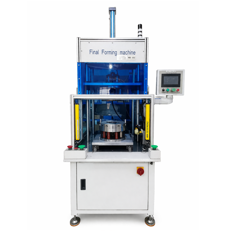
This stator coil forming machine is designed for the final forming stage of stator-coil production. It uses a hydraulic system as its main power source and an in-and-out workstation structure. The supplied description identifies an industrial programmable PLC as the controller for the mold sequence. During the stated final-forming operation, the tooling uses an internal-expansion and external-wrapping end-forming telescopic design. Together, these elements describe a machine intended to shape the finished coil ends after the relevant upstream stator operations have been completed.
For a production team, final forming is not simply a finishing label; it is the point where the workpiece dimensions, the tooling relationship, and the required handling route need to meet. This stator coil forming machine presents the process as a defined hydraulic forming operation rather than a general-purpose press. The hydraulic system, PLC-controlled mold sequence, and in-and-out workstation arrangement give the machine a clear place in a stator manufacturing route. It is most relevant when the stator size and final-forming requirement fall within the published limits.
The hydraulic stator press arrangement uses hydraulic power for the forming action. The source material describes an internal expansion and external wrapping end-forming telescopic design. Internal expansion and external wrapping are practical descriptions of how the final-forming tooling approaches the coil ends; the actual tooling fit should correspond to the stator and process route. This machine is suitable for discussions where final coil geometry, the supported stator envelope, and material flow around the workstation need to be considered together.
PLC-controlled stator forming is useful when a manufacturer wants the forming sequence to be managed through the machine control system rather than described as a manual finishing step. So what does that mean for the production route? It means the stator dimensions, the coil-end condition, and the tooling connection should be supplied when discussing the final-forming configuration. The machine capability is about the stated forming station; upstream coil insertion, insulation work, transport equipment, and the complete line arrangement remain separate considerations.
The following values come from the supplied product description. They identify the stated operating envelope for this motor manufacturing equipment and should be read together, not as isolated values.
| Specification | Published Value |
|---|---|
| Stator outside diameter limit | Up to 250 mm |
| Stator inside diameter limit | 80–140 mm |
| Stator core length limit | 80–300 mm |
| Cylinder displacement | 20 L/min |
| Power supply | 380 V, 50/60 Hz, 1.5 kW |
| Machine weight | Approximately 600 kg |
| Overall dimensions | 950 × 1550 × 2400 mm |
The stator coil forming machine is therefore described for stators with an outside diameter of up to 250 mm, an inside diameter from 80 mm to 140 mm, and a core length from 80 mm to 300 mm. These dimensional limits are useful starting points for matching a workpiece to the forming station. Before a configuration is discussed, the actual stator drawing, coil-end condition, and required process sequence should be aligned with the tooling arrangement.
This motor manufacturing equipment is listed for fuel automotive, new energy vehicle, industrial, elevator, home appliance, pump, and fan applications. Across these applications, the common link is a stator assembly that needs a defined final-forming operation. The machine can be considered where the product route calls for hydraulic final forming after the relevant coil and stator preparation steps.
For automotive and new energy vehicle motor production, the published stator envelope gives engineers a concrete starting point for a particular part family. The PLC-controlled sequence can support structured forming at the station. The workpiece dimensions and tooling details should determine whether the stated arrangement suits the intended production route.
Industrial motors, elevator motors, and home-appliance motors can involve different stator sizes and coil configurations. The listed OD, ID, and core-length ranges provide the first check for an inquiry. A final-forming station should be assessed alongside the coil condition and the handoff from the preceding operation, especially where more than one motor variant is planned.
Pump and fan motor applications are also named in the supplied material. In these use cases, the machine is a focused item for the final coil-forming step. Its hydraulic forming concept and PLC-controlled mold operation provide the product definition; the suitability of a particular part depends on the dimensions and process information supplied for the application.
The machine should be matched to the actual stator, not only to a broad equipment category. The published dimensions, hydraulic main power source, and PLC-controlled mold operation establish the available product information. For an inquiry, share the stator OD, ID, core length, coil-end condition, and the required position of final forming in the production sequence. These details help clarify the machine and tooling discussion while keeping the scope focused on the specified hydraulic forming operation.
Share your stator dimensions, coil-end condition, and required final-forming sequence to discuss the hydraulic final-forming requirement and the appropriate next step.

 EN
