
Electric motors power countless devices in our modern world, from power tools to industrial machinery. At the heart of many motor designs lies a critical component that ensures smooth operation and reliable performance. Understanding how this essential element functions provides valuable insights into motor efficiency and maintenance requirements. This comprehensive guide explores the fundamental principles, construction details, and practical applications that make motors work effectively across various industries.
Understanding Commutator Construction and Design
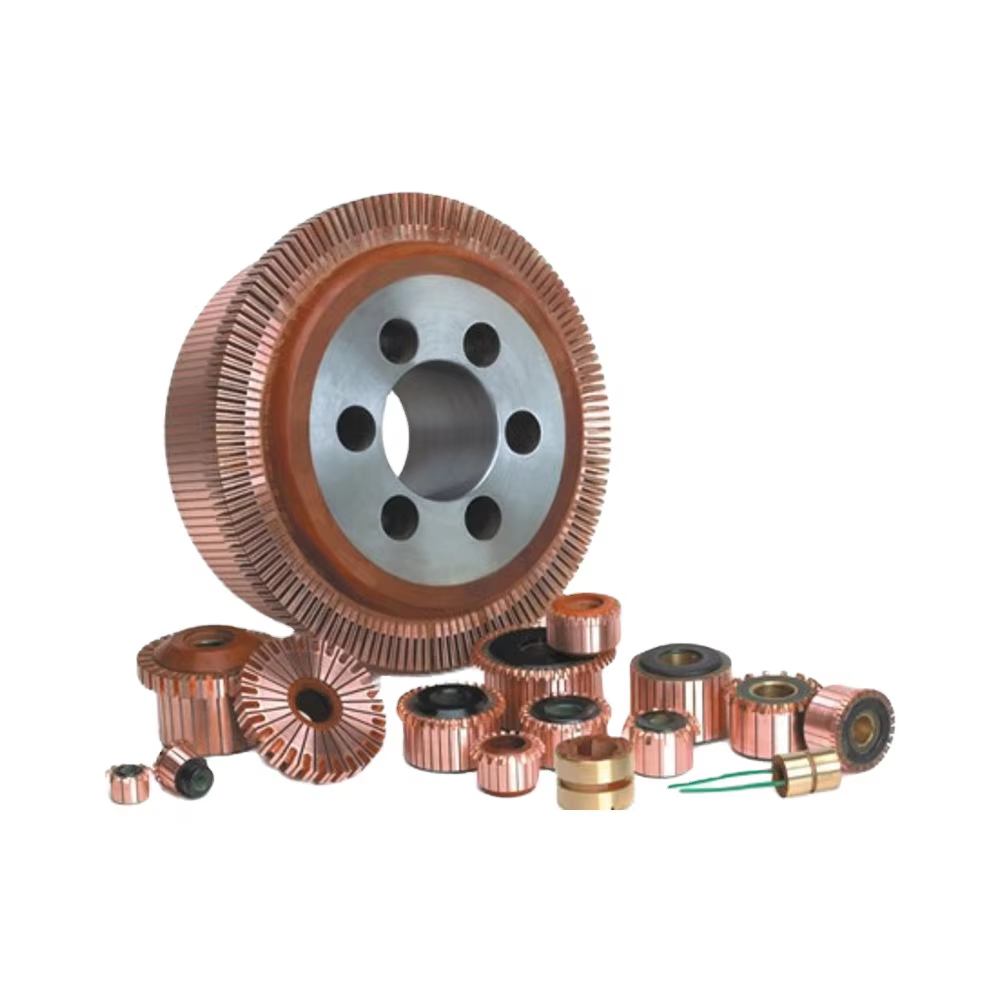
Core Components and Materials
A commutator consists of multiple copper segments arranged in a circular pattern around the motor shaft. These segments are carefully insulated from each other using mica or similar materials to prevent electrical short circuits. The copper material provides excellent electrical conductivity while maintaining durability under constant friction from carbon brushes. High-quality commutators typically feature precise manufacturing tolerances to ensure smooth operation and minimal electrical noise during motor function.
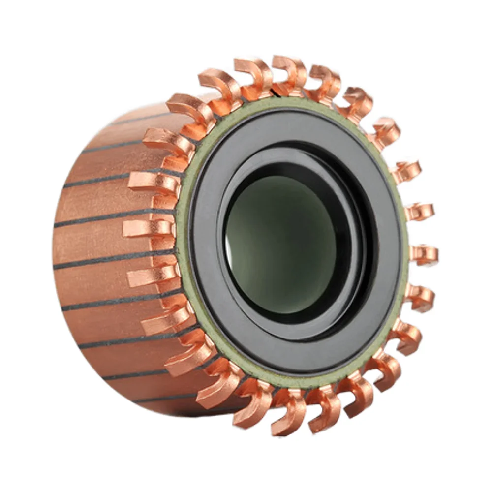
The insulation between segments plays a crucial role in maintaining proper electrical separation. Mica insulation offers superior heat resistance and electrical properties compared to alternative materials. Professional manufacturers often specify the number of segments based on motor applications, with power tools commonly requiring 20 to 24 segments for optimal performance. The segment count directly influences motor smoothness and torque characteristics.
Manufacturing Precision and Quality Standards
Modern commutator manufacturing involves sophisticated machining processes to achieve the tight tolerances required for professional applications. Each segment must be precisely positioned and secured to prevent movement during high-speed operation. The surface finish of copper segments requires careful attention to ensure proper contact with carbon brushes while minimizing wear rates.
Quality control procedures verify dimensional accuracy, electrical continuity, and insulation integrity before final assembly. Professional manufacturers implement rigorous testing protocols to ensure each commutator meets performance specifications. These standards are particularly important for power tool applications where reliability and durability are essential requirements.
Electrical Function and Current Flow Principles
Current Direction and Switching Mechanism
The primary function of a commutator involves switching current direction in motor windings to maintain continuous rotation. As the rotor turns, carbon brushes make contact with different segments in sequence, effectively reversing current flow at precisely timed intervals. This switching action creates the magnetic field interactions necessary for sustained motor operation.
The timing of current switching directly affects motor efficiency and performance characteristics. Proper commutator design ensures smooth transitions between segments without significant voltage spikes or electrical arcing. This smooth operation reduces electromagnetic interference and extends the operational life of both brushes and commutator segments.
Magnetic Field Interaction and Torque Generation
Current flowing through rotor windings creates magnetic fields that interact with permanent magnets or field windings in the stator. The commutator ensures these magnetic fields maintain proper orientation relative to the stator fields, generating consistent torque output. Without proper commutator function, motors would experience reduced efficiency and irregular operation.
The strength and timing of magnetic field interactions determine motor torque characteristics and speed regulation. Professional-grade commutators maintain precise electrical contact to ensure consistent magnetic field strength throughout the rotation cycle. This consistency is particularly important in applications requiring steady torque output and reliable speed control.
Applications in Power Tools and Industrial Equipment
Power Tool Integration and Performance Requirements
Power tools represent one of the most demanding applications for commutator technology. Angle grinders, circular saws, and drilling equipment require commutators capable of handling high current loads while maintaining smooth operation under variable load conditions. The 24-segment configuration commonly found in professional power tools provides the optimal balance between performance and manufacturing cost.
Professional power tool manufacturers specify commutator designs based on expected duty cycles and performance requirements. Heavy-duty applications require commutators with enhanced copper alloys and improved insulation materials to withstand extended operation periods. The groove design and segment spacing influence heat dissipation and electrical contact quality during high-load operation.
Industrial Motor Applications and Specifications
Industrial motors often utilize larger commutators with increased segment counts to handle higher power requirements and provide smoother operation. Manufacturing equipment, conveyor systems, and processing machinery rely on commutator motors for variable speed control and precise torque regulation. These applications demand exceptional reliability and extended service intervals.
Industrial commutator specifications typically include enhanced materials and specialized coatings to resist contamination and corrosion. Operating environments in manufacturing facilities expose motors to dust, moisture, and chemical vapors that can degrade standard commutator materials. Professional-grade commutators incorporate protective measures to maintain performance under these challenging conditions.
Maintenance Practices and Performance Optimization
Inspection Procedures and Wear Assessment
Regular commutator inspection helps identify wear patterns and potential issues before they affect motor performance. Visual examination should focus on segment wear, insulation condition, and signs of electrical arcing or overheating. Uniform wear across all segments indicates proper brush alignment and adequate lubrication of motor bearings.
Measuring commutator runout and surface finish provides quantitative data about component condition. Excessive runout causes uneven brush contact and accelerated wear rates. Professional maintenance procedures include resurfacing operations when wear exceeds specified limits while maintaining proper segment isolation and electrical continuity.
Cleaning and Restoration Techniques
Proper cleaning removes carbon deposits and contamination that can cause electrical problems and reduced performance. Specialized cleaning compounds dissolve built-up residue without damaging copper segments or insulation materials. Cleaning frequency depends on operating conditions and duty cycle requirements of specific applications.
Restoration procedures may include light machining to restore proper surface finish and dimensional accuracy. Professional restoration maintains the original commutator specifications while extending service life. These procedures require specialized equipment and expertise to ensure proper results without compromising motor performance.
Common Issues and Troubleshooting Solutions
Electrical Problems and Performance Symptoms
Commutator-related issues often manifest as excessive sparking, reduced motor power, or irregular operation. Electrical arcing between brushes and segments indicates poor contact conditions or contamination buildup. These symptoms typically worsen under load conditions and can lead to permanent damage if not addressed promptly.
Performance degradation may result from worn segments, damaged insulation, or improper brush alignment. Diagnostic procedures should systematically evaluate each potential cause to identify the root problem. Professional troubleshooting techniques include electrical measurements and visual inspection to pinpoint specific issues requiring attention.
Replacement Criteria and Selection Guidelines
Commutator replacement becomes necessary when wear exceeds manufacturer specifications or when electrical problems cannot be resolved through maintenance procedures. Selection criteria should consider original equipment specifications, application requirements, and expected service life. Professional replacement ensures compatibility and optimal performance restoration.
Quality replacement commutators must meet or exceed original specifications for segment count, materials, and dimensional accuracy. Professional manufacturers provide detailed specifications and application guidance to ensure proper selection. Installation procedures require careful attention to alignment and electrical connections to achieve optimal results.
Technology Advances and Future Developments
Material Improvements and Enhanced Durability
Recent advances in commutator technology include improved copper alloys and enhanced insulation materials that provide better performance under demanding conditions. Advanced manufacturing techniques enable tighter tolerances and more consistent quality across production runs. These improvements directly benefit end users through extended service intervals and improved reliability.
Specialized coatings and surface treatments offer additional protection against wear and contamination. Professional-grade commutators increasingly incorporate these advanced features to meet the demanding requirements of modern power tools and industrial equipment. Research continues into new materials and manufacturing processes that could further improve performance and durability.
Integration with Modern Motor Designs
Modern motor designs increasingly emphasize efficiency and environmental considerations while maintaining performance standards. Commutator technology continues evolving to support these objectives through reduced friction losses and improved electrical characteristics. Integration with electronic control systems provides additional opportunities for optimization and performance enhancement.
Future developments may include smart commutator designs with integrated sensors for condition monitoring and predictive maintenance. These technologies could provide real-time feedback about commutator condition and performance, enabling proactive maintenance strategies that maximize equipment uptime and reduce operational costs.
FAQ
How long does a typical commutator last in power tools?
Commutator life in power tools varies significantly based on usage patterns and operating conditions. Professional-grade tools with quality commutators typically provide hundreds of operating hours under normal conditions. Heavy-duty applications or extreme operating environments may reduce service life, while proper maintenance and appropriate usage can extend operational periods. Regular inspection helps identify wear patterns and optimize replacement timing.
What causes excessive sparking at the commutator?
Excessive sparking usually indicates poor electrical contact between brushes and commutator segments. Common causes include worn or contaminated segments, improper brush alignment, or damaged insulation between segments. Environmental factors such as dust accumulation or moisture can also contribute to sparking problems. Professional diagnosis should evaluate all potential causes to determine the most appropriate corrective action.
Can commutators be repaired or must they be replaced?
Many commutator problems can be addressed through professional repair and restoration procedures. Light wear and contamination often respond well to cleaning and resurfacing operations. However, severe wear, damaged insulation, or segment separation typically require complete replacement. Professional evaluation helps determine whether repair or replacement provides the most cost-effective solution for specific situations.
How do I select the correct replacement commutator for my application?
Proper commutator selection requires matching original equipment specifications including segment count, dimensions, and electrical ratings. Professional suppliers provide application guides and technical support to ensure correct selection. Key considerations include motor voltage, current requirements, and expected duty cycle. Installation compatibility and mounting requirements must also be verified to ensure proper fit and function in the specific application.